
Feature
Built the way it is fabricated.
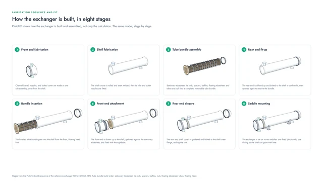
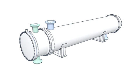
Beyond the calculation, PlutoHX shows the order in which the exchanger is made and put together, in eight stages.
The eight stages
From the front end to the saddles.
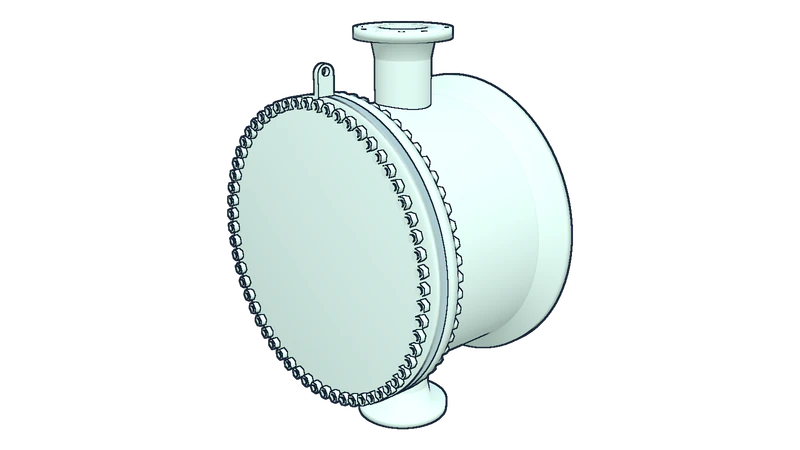
Stage 1 of 8
Front end fabrication
Channel barrel, nozzles, and bolted cover are made as one sub-assembly, away from the shell.
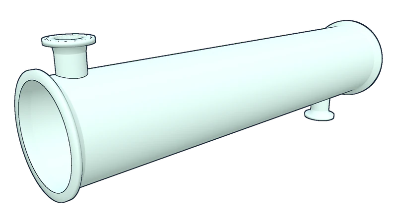
Stage 2 of 8
Shell fabrication
The shell course is rolled and seam welded, then its inlet and outlet nozzles are fitted.
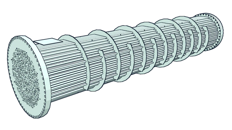
Stage 3 of 8
Tube bundle assembly
Stationary tubesheet, tie rods, spacers, baffles, floating tubesheet, and tubes are built into a complete, removable tube bundle.
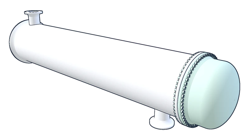
Stage 4 of 8
Rear end fit-up
The rear end is offered up and bolted to the shell to confirm fit, then opened again to receive the bundle.
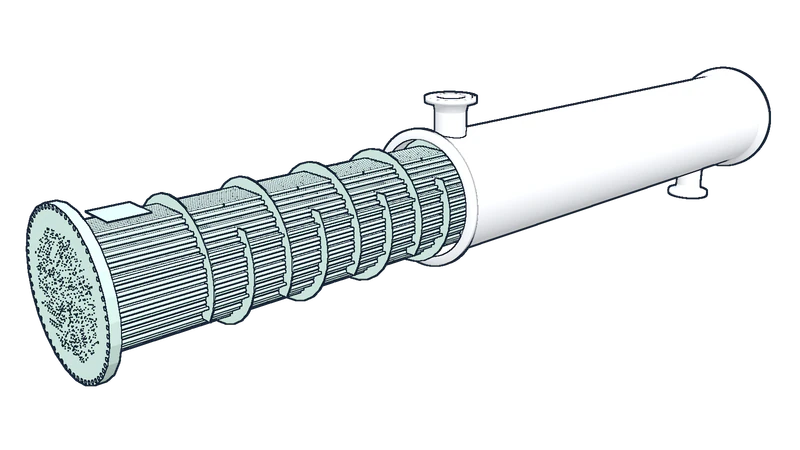
Stage 5 of 8
Bundle insertion
The finished tube bundle goes into the shell from the front, floating head first.
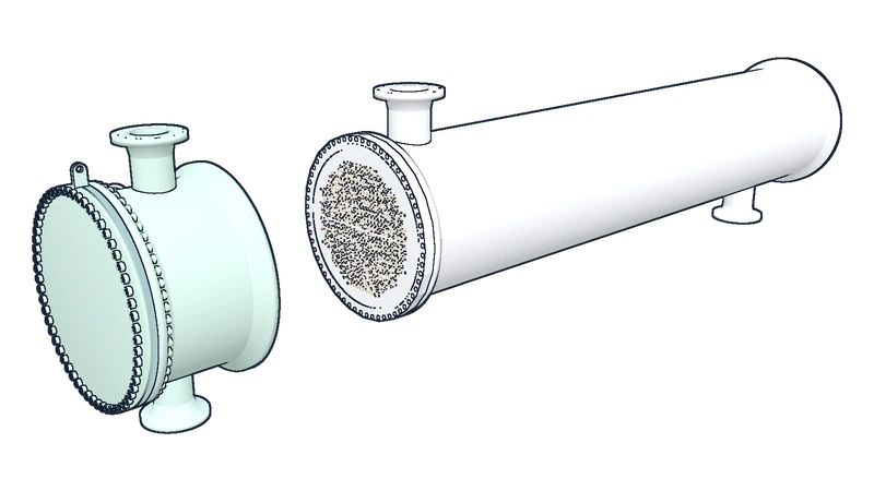
Stage 6 of 8
Front end attachment
The front end is drawn up to the shell, gasketed against the stationary tubesheet and fixed with through-bolts.
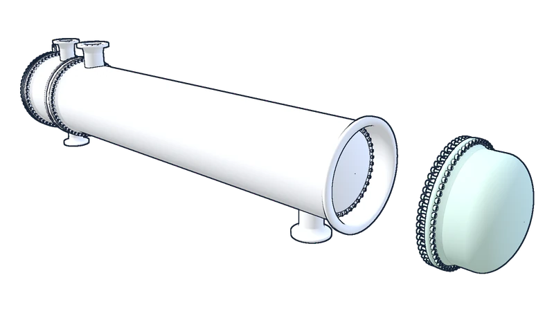
Stage 7 of 8
Rear end closure
The rear end (shell cover) is gasketed and bolted to the shell's rear flange, sealing the unit.
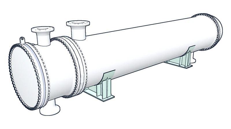
Stage 8 of 8
Saddle mounting
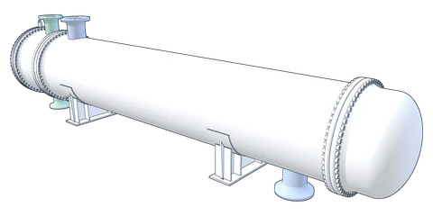
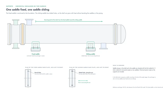
The exchanger is set on its two saddles: one fixed (anchored), one sliding so the shell can grow with heat.
Inside stage 3
How the tube bundle is put together.
The owner’s build order for the bundle:
Stationary tubesheet
The bundle starts from the tubesheet at the channel end.
Tie rods
The tie rods are fixed into the stationary tubesheet.
Spacers
Spacers on the tie rods set the distance between the baffles.
Baffles
The single segmental baffles go onto the tie rods, one after another.
Nuts
Nuts hold the baffle stack in place.
Floating tubesheet
The tubesheet at the rear end goes on next.
Tubes
The tubes are passed through the baffles and both tubesheets.
Floating head
The floating head closes the rear of the bundle.
Why it helps
For the shop, and for the site.
The stages show the fabricator the order of work, and the owner-operator what maintenance involves: the tube bundle of the reference exchanger is removable (TEMA type T), and its two saddles are one fixed and one sliding.
In PlutoHX an assembly sequence timeline plays the same build step by step beside the model.
Coming Winter 2026
We would be glad to show you PlutoHX.
PlutoHX launches at the end of this year. A live demo shows how it fits the way your team works.
Visit us at the booth for a deep dive into PlutoHX.