
Guide
How Appendix 2 sizes a girth flange.
Appendix 2 works in order: the loads on the bolts, the bolt area they need, and then a flange thickness that carries them.
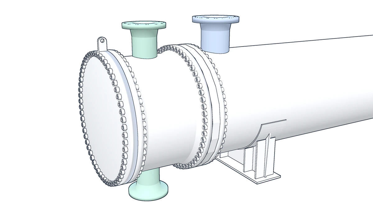
The example flange
An integral girth flange, to scale.
The girth flange of the reference exchanger, with the symbols Appendix 2 uses for it.
In order
From the gasket to the thickness.
The gasket
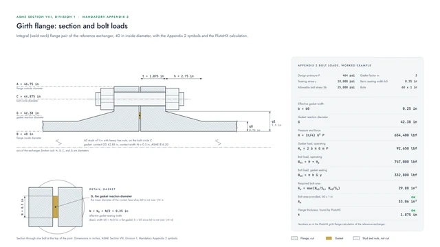
The effective gasket width b equals the basic width b0, 0.25 in, because b0 is not over 1/4 in. The gasket load acts on the reaction diameter G, 42.38 in.
The pressure
At 464 psi, the pressure end force H on the area inside G comes to 654,400 lbf.
Operating
In operation the bolts carry H plus the gasket load Hp, which uses the gasket factor m of 3 and comes to 92,650 lbf. So Wm1 is 747,000 lbf.
Seating
To seat the gasket at its seating stress y of 10,000 psi, before any pressure, the bolts need Wm2 of 332,800 lbf.
The bolt area
The larger load over the allowable bolt stress of 25,000 psi gives the required area Am of 29.88 in². Sixty bolts of 1 in give 33.06 in², enough to meet it.
The thickness
With the bolting settled, the engine finds the flange thickness: 1.875 in.
See the bolt sets side by side
The flanges page has the calculation sheet and a what-if with three bolt sets.
Coming Winter 2026
We would be glad to show you PlutoHX.
PlutoHX launches at the end of this year. A live demo shows how it fits the way your team works.
Visit us at the booth for a deep dive into PlutoHX.